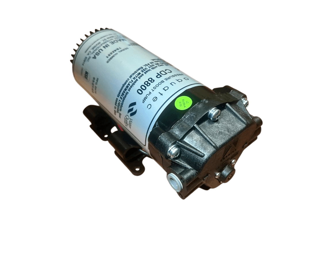
Aquatec 8800 Electric Diaphragm Pump
The Aquatec 8800 electric diaphragm pump is designed for industrial applications and OEM systems requiring stable flow and controlled pressure. The 3-chamber self-priming design ensures reliable operation and dry running capability.
- Power supply: 24 VDC
- Max flow rate: up to 2.35 l/min
- Max pressure: up to 5.5 bar
- Max fluid temperature: 77 °C
- Self-priming: up to 2.1 m
- Weight: 2.72 kg
- Certifications: NSF Standard 58
- Download datasheet
Speak with a technical consultant for the 8800 Series
Applications
The Aquatec 8800 Series is designed for liquid transfer and pressurization in industrial applications and water treatment systems..
- Reverse osmosis systems (RO booster pumps)
- Water filtration systems
- Industrial process equipment
- OEM integrated systems
- Liquid transfer in low to medium flow applications
The datasheet indicates pre-filter water treatment for reverse osmosis systems as a typical application.
Technical specifications
The indicated values may vary depending on configuration and operating conditions.
Performance
Performance curves
| Pressure (bar) | Flow 88X0 (l/min) | Current 88X0 (A) | Flow 88X1 (l/min) | Current 88X1 (A) | Flow 88X2 (l/min) | Current 88X2 (A) | By-pass (bar) | Code |
|---|---|---|---|---|---|---|---|---|
| 5.5 | 0.83 | 0.92 | 1.14 | 0.99 | 1.51 | 1.24 | 7.6 | J |
| 4.8 | 1.14 | 0.85 | 1.25 | 0.90 | 1.63 | 1.13 | 6.9 | I |
| 4.1 | 1.25 | 0.77 | 1.36 | 0.83 | 1.74 | 1.02 | 6.2 | H |
| 3.4 | 1.32 | 0.70 | 1.40 | 0.74 | 1.85 | 0.91 | 5.5 | G |
| 2.8 | 1.40 | 0.62 | 1.48 | 0.65 | 1.89 | 0.79 | 4.8 | F |
| 2.1 | 1.48 | 0.53 | 1.51 | 0.56 | 1.97 | 0.68 | 4.8 | F |
| 1.4 | 1.59 | 0.45 | 1.63 | 0.47 | 2.12 | 0.55 | 4.8 | F |
| 0.7 | 1.70 | 0.35 | 1.78 | 0.37 | 2.27 | 0.41 | 4.8 | F |
| 0 | 1.89 | 0.32 | 1.93 | 0.34 | 2.35 | 0.38 | 4.8 | F |
Thermal behavior (Heat Rise)
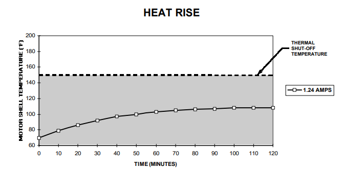
The Heat Rise chart shows the increase in motor surface temperature over time as a function of current draw. The shaded area indicates configurations that can operate continuously without the need for periodic cooling.
Dimensional drawings
Dimensional drawings allow correct mechanical integration of the pump within the system. Dimensions are expressed in millimeters (mm).

Other products in the same series
Speak with one of our technical consultants
Our specialists can help you verify the pump’s compatibility with your application or recommend the most suitable model.